

重新开始出发
【笔记】【百人计划】图形4.3 实时阴影算法
GAMES202这部分的笔记会详细一些
https://xzyw7.github.io/post/real-time-shadows/
一、基于图片的实时阴影
1.1 平面投影阴影
Shadow Volume?
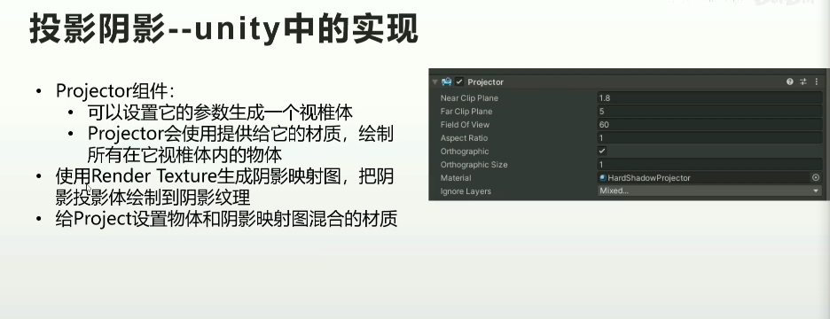
- Unity-Projector组件
1.2 阴影映射
略
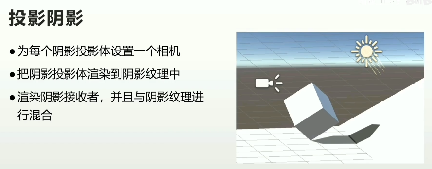
1.3 屏幕空间阴影映射
- 渲染屏幕空间深度图
- 从光源渲染shadow map
- 屏幕空间做一次阴影收集计算(Shadows Collector),得到一张屏幕空间阴影纹理
- 绘制物体的时候,用物体的屏幕UV坐标,采样该屏幕空间阴影纹理
二、Shadow Mapping的优化
2.1 自阴影问题
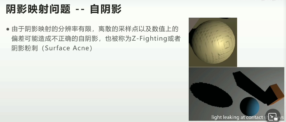
不建议叫Z-fighting
- 当比较深度时,为了避免表面自阴影,需要设置容错阈值
- 深度偏移(Depth Bias)
- 法线偏移(Normal Bias)
- 偏移过大会出现阴影悬浮,也叫做Peter Panning
自阴影的优化/偏移优化
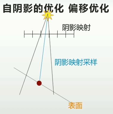
由于shadow map采样率,这一片都对应了同一个深度
- 深度偏移:增加深度偏移使该像素向光源靠近
- 法线偏移沿法线方向向外偏移
- 偏移单位是shadow map的纹素
- 在Shadow Receive计算阶段,逐像素进行
- 只会在阴影深度测试时使用,不影响场景
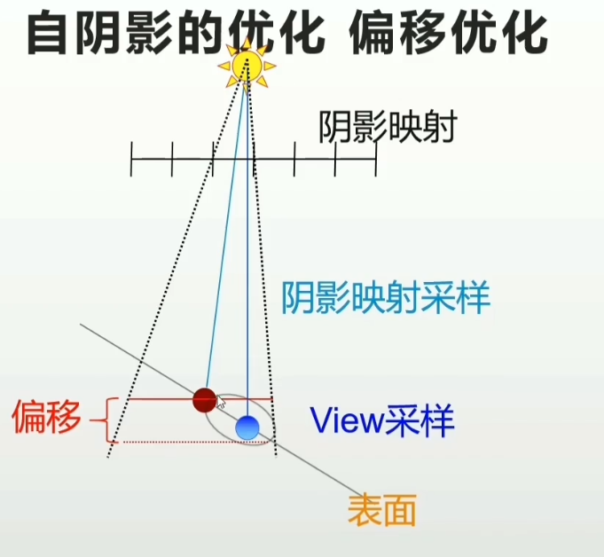
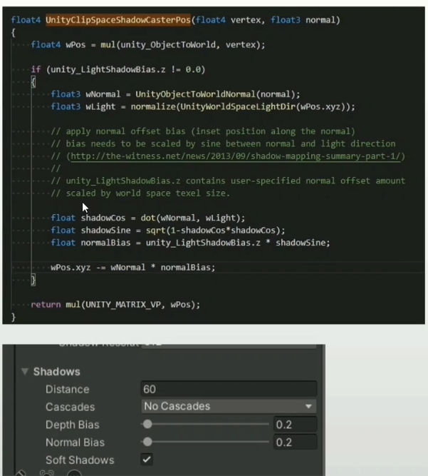
Unity中的偏移优化
- Shadow Caster阶段基于顶点的Normal Bias
- 在Shadow Caster阶段让遮蔽物进行反向偏移
- 优点:性能高
2.2 走样问题
- 初始采样
- 渲染shadow map
- 透视走样
- 重采样
- 摄像机视角对采样信号(shadow map)重采样
2.2.1 透视走样的原因及解决方案
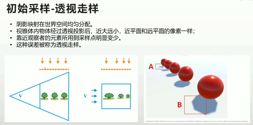
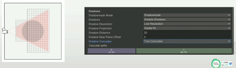
级联阴影映射
- 透视走样最有效的解决方案
- 把视锥体分割为多个子视锥体
- 为每个子视锥体计算独立的相等大小的Shadow map
2.2.2 重采样的原因及解决方案
- 阴影映射是一张动态生成的纹理
- 滤波-纹理采样误差的解决方案
- 阴影的滤波
- 使用一部分Shadow map采样点来计算某个指定View采样点的最终阴影结果
- 阴影的滤波
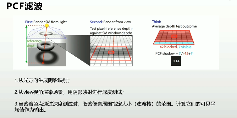
- 采样数
- 规则滤波,3x3或5x5
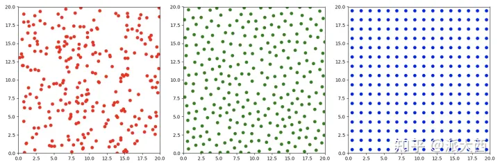
- 采用Poisson Disk等的形式来分布一定数量的采样点
- 滤波核函数
- 高斯函数作为滤波核函数
作业
- 总结实时阴影的优化方案
- 尝试自己实现一套阴影系统
直接放GAMES202的作业在这了
https://xzyw7.github.io/post/guo-cheng-ji-lu-games202-huan-jing-pei-zhi-yu-shi-shi-yin-ying/
参考资料
[1] https://www.bilibili.com/video/BV1Jf4y1P7ch
【技术美术百人计划】图形 4.3 实时阴影介绍
【过程记录】【GAMES202】环境配置与实时阴影
作业0
作业0就配置下环境,但是会遇到模型有时候加载不出来的问题,论坛里说得很清楚。
https://games-cn.org/forums/topic/zuoye0-jieguobuwendingyoushimoxingxianshibuquan/

由于异步处理,如果这张材质图片是后加载的就看不见了,因此解决操作是把它预先加载。
其次是在框架上编写Phong模型的shader,跟着说明做就行了。
作业1
CalcLightMVP
第一步需要完成shadow mapping的部分,计算方向光下的MVP矩阵。
1 | CalcLightMVP(translate, scale) { |
这里提供了translate和scale的参数,没有rotation,那就不用。
并且我们在Mesh Render当中可以找到camera计算MVP的部分
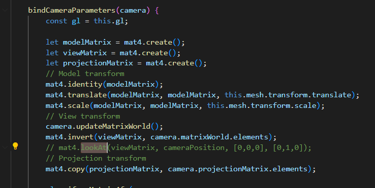
Model的部分可以直接照抄了,这里也是没有Rotation的,可见估计是为了方便,省去了四元数等等的旋转计算,就没有做旋转变换。
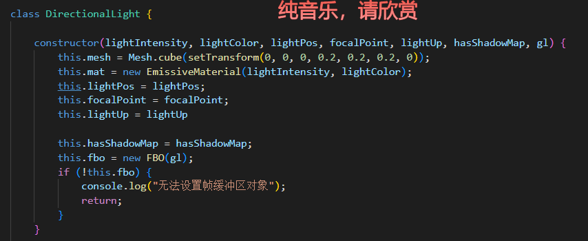
接下来是View矩阵的部分。在方向光的构造函数中,提供了一些东西,有lightPos和focalPoint,我们就可以计算出front,有up,那么view矩阵就很好算出来了。
但是我一直没有找到这个框架矩阵运算的api,只能看里面已经有的怎么用我就怎么用……上面有个lookAt的方法,那就用它了。

猜也很好猜(输出,相机位置,focal位置,up向量)
还是给找到了,矩阵运算的api用了一个gl-matrix-min的库,这个东西就来自于gl-matrix,百度搜到文档
https://glmatrix.net/docs/module-mat4.html
最后变成就这么几行
1 | CalcLightMVP(translate, scale) { |
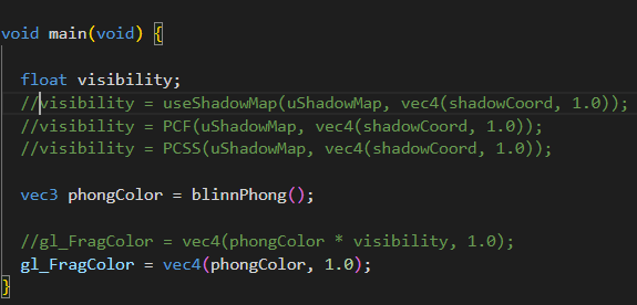
useShadowMap
下一步就是完成fs中的可见性计算,框架给我们准备得很好,可以看到包括后面进阶部分的PCF和PCSS,都封装好了,只需要填函数就可以了。
首先需要完成的是useShadowMap来做一个简单的shadow map
首先我们要用shadow Coord去采样shadow Map来获得着色点在灯光视角下的该位置的最小深度。因此采样我们应该在灯光的齐次裁剪空间坐标下。
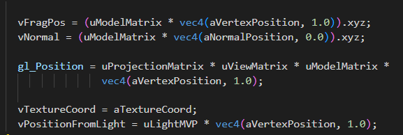
顶点着色器已经把它做好了,就是vPositionFromLight。
我们也可以在shadowFragment当中看到在light pass中对深度的处理
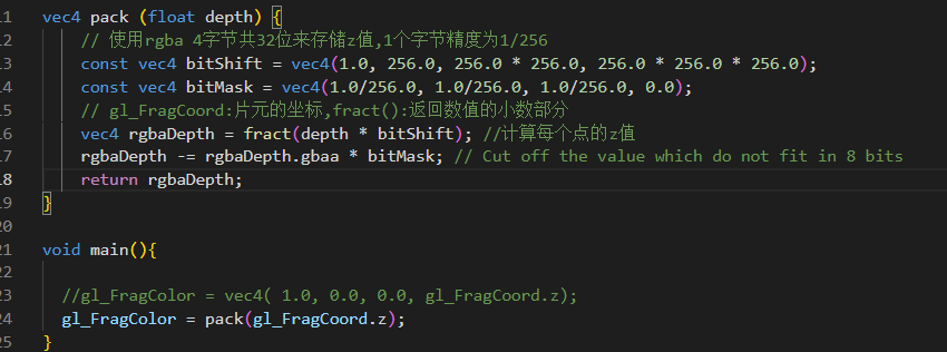
将片元的深度进行了pack。注意这里的深度,是在片元着色器阶段,因此,齐次裁剪空间的坐标需要经过透视除法。(虽然正交投影没有影响)
还要注意,采样贴图需要在0-1完成,这使得我们需要做一个映射操作
1 | vec3 shadowCoord = (vPositionFromLight.xyz/vPositionFromLight.w) * 0.5+vec3(0.5); |
但是问题来了,在learnopengl中,因为深度贴图储存范围在0-1,所以深度也需要做这个映射,我们这里把深度用pack的方法保存存了,为什么还要做这个映射呢?不是只需要映射xy就行了吗?
问题的根节是,framebuffer中存储的深度到底是什么深度?pack暂且不管,也就是说,gl_FragCoord.z到底是什么?首先像上面说的,肯定是在NDC空间的z经过了透视除法之后,但这一部分也是在[-1,1]^3中,(由于平台差异,如D3D的NDC空间的z就是[0,1])那么为了写入深度缓冲,Opengl自己做了这一部分的映射
https://zhuanlan.zhihu.com/p/66175070
这一点只要记住就行了,总得来说,gl_FragCoord.z就是深度缓冲中的值,也就是[-1,1]=>[0,1]变换过后的NDC的z值。总之,这里虽然整体*0.5+0.5,做了变换,但意义是不同的。
那么最后在shadow map的部分,提取出深度拿来比较一下就好了。
1 | float useShadowMap(sampler2D shadowMap, vec4 shadowCoord){ |
这一部分算是完成了。
PCF
这一部分也很容易,跟着learnopengl也能做,不过作业框架中提出,我们可以对比一下两种采样的区别
1 | void uniformDiskSamples( const in vec2 randomSeed ) { |
这里做的是单位圆盘上的随机采样,把一个vec2储存到了poisonDisk的数组上。那么我们只需要在采样shadowmap的纹理坐标上,增加一个这个位置的样本即可。要注意的是我们的纹理采样是在0-1范围上的,因此这个位置也应该根据纹素大小进行放缩(如果把纹素大小看作单位长度的话)。这一部分learnopengl直接用了textureSize的API,但我们使用的opengl ES版本似乎不支持这个api,但是能够在engine.js中找到对framebuffer的定义
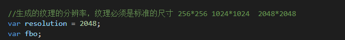
因此只需要除以2048即可。我们也可以通过对这个采样范围进行任意的放缩,相当于不同size的kernel。(比较喜欢这个框架的采样的处理方式,learnopengl中的遍历纹素就太笨重了)。
1 | float PCF(sampler2D shadowMap, vec4 coords) { |
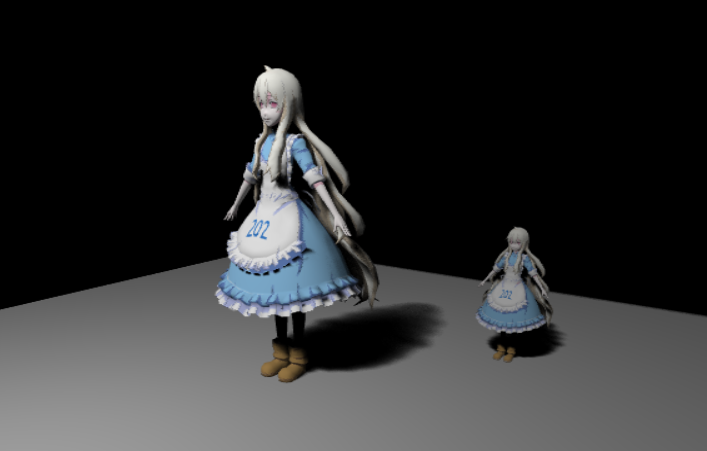
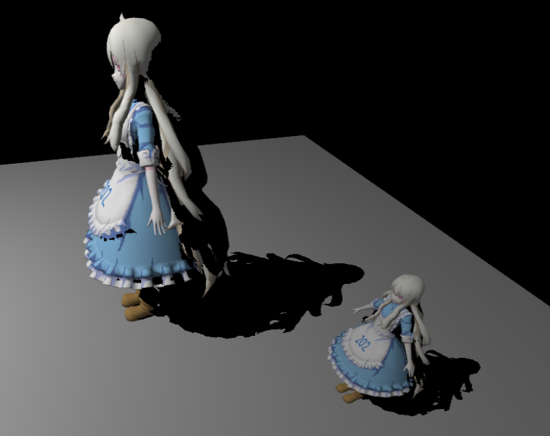
效果如下
边缘是被模糊了,但是如果我们想要更多的模糊,会发现模型其他部分也受到了影响,出现一些噪声。
Uniform:
Poisson:
关于泊松圆盘采样,这里说得很好,一张图就可以解释
https://zhuanlan.zhihu.com/p/484414050
PCSS
1 | float findBlocker( sampler2D shadowMap, vec2 uv, float zReceiver ) { |
一些小小的filterSize的可视化
可以注意到这种边缘的地方实际上存在artifacts

解决方法如下
https://games-cn.org/forums/topic/zuoye1-dibanbianyuanjianbianhuisejiejuefangfa/
https://games-cn.org/forums/topic/zuoye1guanyuplanebianjiezaodiandecaiceyujiejue/
(但也不能完全解决)
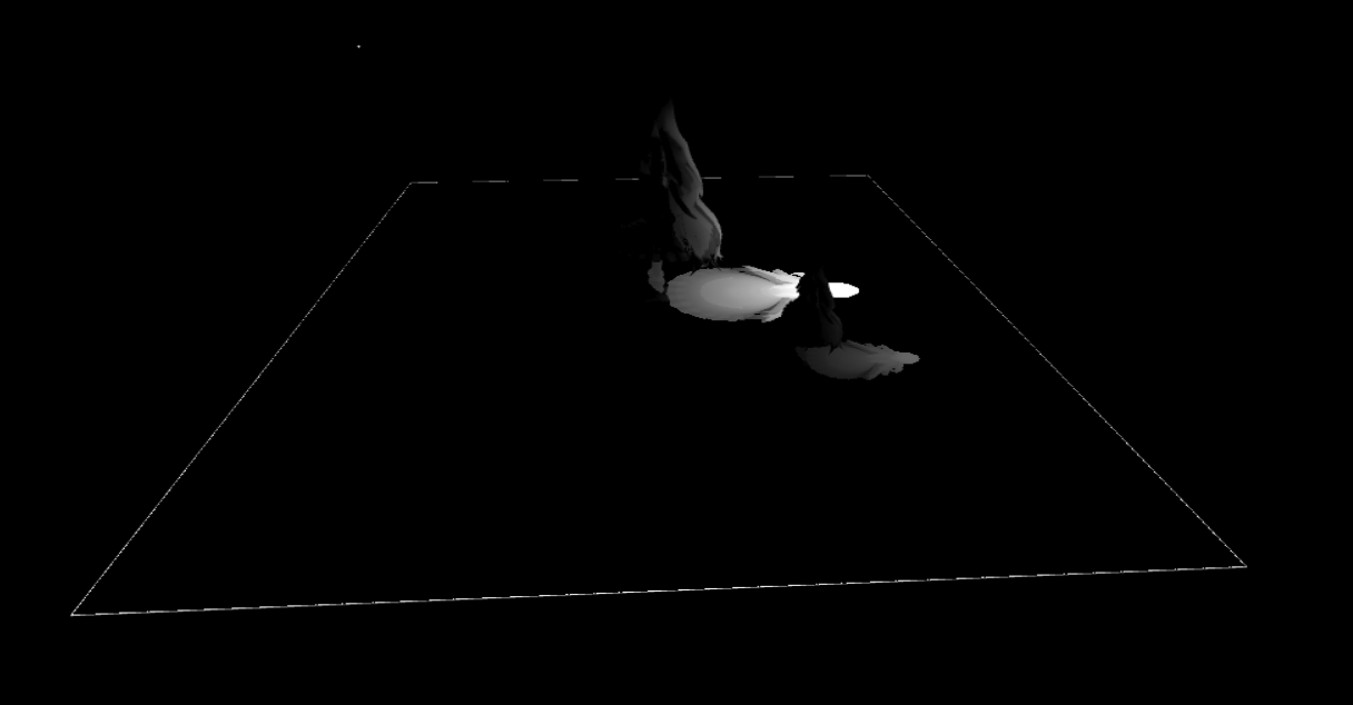
Shadow的可视化
增加一点高质量的
下一部分就直接进入PRT了,就不接在这儿了,不然太长了
【笔记】【百人计划】图形4.5 Dof景深基础
图形4.5 Dof景深基础
一、景深

- 景深
- 相机对焦点前后相对清晰的成像范围。
- 虽然透镜只能将光聚到一个固定的距离(焦距),远离此点则会逐渐模糊,但在一段特定的距离内,模糊的程度是无法察觉的,这段距离称之为景深。
- 当焦点设在超焦距处时,景深会从超焦距的一半延伸到无限远,对于一个固定的光圈来说,这是最大的景深。

脱焦的点扩大到超过像素大小以后,就会出现模糊
二、作用
- 选择性突出或强调画面中的一部分,吸引观察者的注意力到画面中清晰对焦的部分,忽略其他模糊部分的细节
- 强调所拍摄场景的深度,增加画面的层次立体感
- 艺术意境的表达
- 表达主观的视线。在电影学中,通过调节浅景深的镜头,使之对焦在不同位置上,来表示某个人的主观视线的转移
- 交代人物之间的关系。在电影学中,通过景深聚焦位置的变化来表达前景和背景人物之间的关系
三、移动端景深实现
- 制作思路
- 模拟景深制作mask
- 模糊场景
- 正常场景
- 合并

计算时对于从深度图中获取深度的处理,需要乘以远裁面的大小,获得绝对的相机深度。
1 | half depth = Linear01Depth(tex2Dd(_CameraDepthTexture,i.uv))*_ProjectionParams.z; |
(这一部分感觉可以替换成恢复线性深度的处理)
因为我们不希望远裁面的位置影响到我们的景深效果(吗?我觉得这一点可以再斟酌一下)
然后通过焦距设置以及该深度计算景深Mask
1 | float focusNear = _FocusDistance - _DepthOfField; |
搞了一个如下的Mask效果,靠近焦距就不模糊(0),远离焦距就模糊(1)

接下来的计算就很自然了,卷积,然后根据mask和原图进行插值。

通过降采样多次迭代处理
1 | void OnRenderImage(RenderTexture src, RenderTexture dest) { |
可见在实际操作中,为了获得好的模糊效果,是在第一个pass中完成多次的降采样与卷积,然后在第二个pass中进行mask的提取与插值

四、高级景深效果思路拓展

颜色泄露

模糊不连续缺陷
焦点在背景时,前景会被截断——前后景分离

散景的模拟

作业
- 实现景深效果
- 分析官方后处理插件PPS中的景深实现
参考资料
[1] https://www.bilibili.com/video/BV1dv411u7KA
【技术美术百人计划】图形 4.5 Dof景深基础
【笔记】【百人计划】图形4.4 抗锯齿概述
图形4.4 抗锯齿概述
一、锯齿的产生

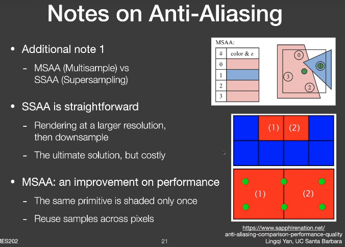
二、基本的抗锯齿
MSAA

SSAA

(这个实例图好像有哪里不对劲,意思到了就行了)
TAA
- 把每次采样过程分布到每一帧去,每一帧都平均前面几帧保存下来的数据
- 每一帧会有一定的偏移,继承了MSAA采样
- 用Motion Vector保存每帧移动的偏移

FXAA
FXAA快速近似抗锯齿(Fast Approximate Anti-Aliasing)
- 利用边缘检测进行有效的模糊混合
- 在后处理完成,不依赖硬件支持
抗锯齿速度排序
- FXAA
- TAA
- MSAA
- SSAA
三、更多的抗锯齿
- 前向渲染
- SSAA
- MSAA
- CSAA
- RGSS
- 延迟渲染
- FXAA
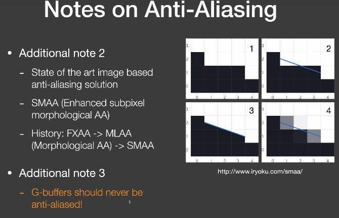
- MLAA
- SMAA
- 基于深度学习
- DLSS
https://zhuanlan.zhihu.com/p/106341932
作业
- 对比各个抗锯齿方案的优劣(效果、效率)
- (有能力的可以进行各个方案真机测试)
参考资料
[1] https://www.bilibili.com/video/BV1VR4y1J7KT
【技术美术百人计划】图形 4.4 抗锯齿概论
【笔记】【GAMES202】A Glimpse of Industrial Solutions
A Glimpse of Industrial Solutions
Anti-aliasing
Temporal Anti-Aliasing(TAA)
Why aliasing
- 光栅化中逐像素采样率不足
- 因此,终极解决方案是使用更多样本
TAA
- 复用上一帧的样本
- Almost exactly the same as in RTRT
Notes on AA
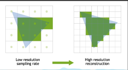
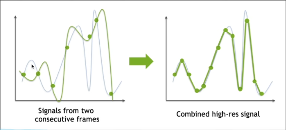
Temporal Super Resolution
- Super resolution(super sampling)
- Literal understanding: increasing resolution
- Source 1(DLSS 1.0): out of nowhere/completely guessed
- Source 2(DLSS 2.0): from temporal information
- Key idea of DLSS 2.0
- TAA-like application
- Temporally reuse samples to increase resolution
Super sampling and DLSS
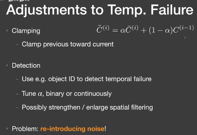
- DLSS2.0 Main Problem
- Upon temporal failure, clamping is no longer an option
- Because we need a clear value for each smaller pixel
- Key is how to use temporal info smarter than clamping
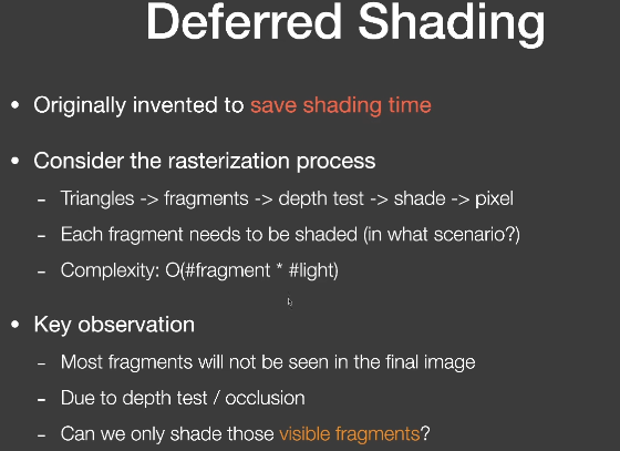
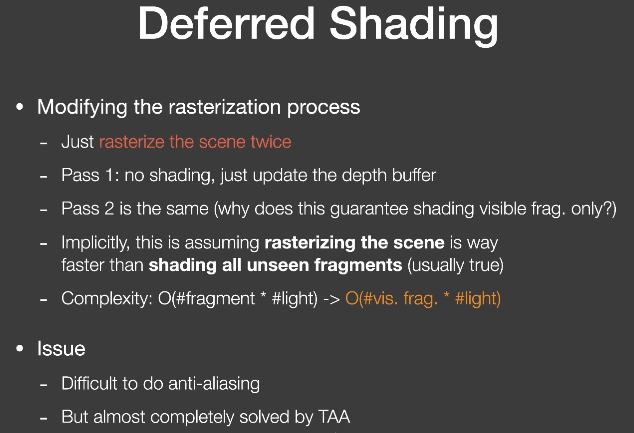
Deferred Shading
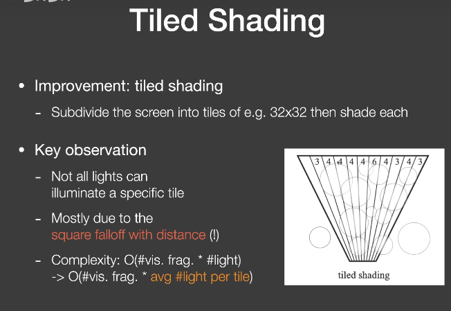
Tiled Shading
- Improvement: tiled shading
- subdivide the screen into tiles
- Key observation
- Not all lights can illuminate a specific tile
- Mostly due to the square falloff with distance
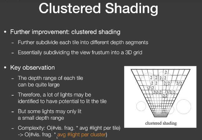
Clustered Shading
除了屏幕空间的分块,还要在深度上分割
LoD solutions
- Choosing the right lod to use can save computation
- The use of multiple lod
- Called “Cascaded” by the RTR industry
- EX:
- Cascaded shadow maps
- Cascaded LPV
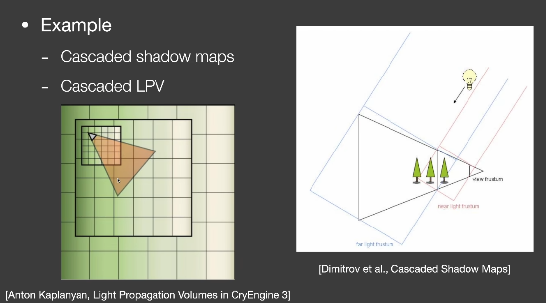
- Key challenge
- Transition between different Levels
- Usually need some ==overlapping and blending== near boundaries
- Another Example: Geometric LOD
- 生成一套不同三角面数的简化的模型
- 基于相机距离选择合适的物体(or part of obj, s.t. no triangle will be larger than a pixel)
- Popping artifacts(突然出现)——leave it to TAA
- Nanite in UE5(动态选取Lod)
- Technical difficulties
- 不同的部位使用不同层级,如何处理接缝cracks?
- 动态加载(load)和调度(schedule)不同层级,如何最好地利用缓存(cache)和带宽(bandwidth)?
- Representing geometry using triangles or geometry textures(几何纹理)
- Clipping and culling for faster performance
GI Solutions
Uncovered Topic
【笔记】【GAMES202】Real-time Ray Tracing实时光线追踪
Real-time Ray Tracing实时光线追踪
1. Real-time Ray Tracing实时光线追踪
2018年,NVIDIA发布GeForce RTX系列(Turing架构)
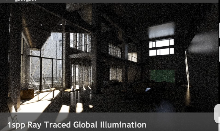
RTX在硬件上可以发射10 Giga rays per second(RT core)
但是在实际应用中只能做到 1 sample per pixel。
1SPP path tracing =
- 1 rasterization(primary) + (实际用光栅化方法来代替第一条光线)
- 1ray(primary visibility) +
- 1ray(secondary bounce)+
- 1ray(secondary visibility)
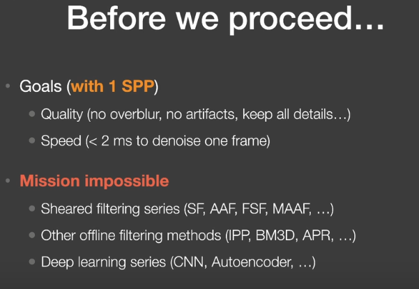
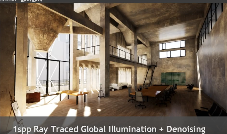
1SPP存在极大噪声,RTRT关键部分在于==Denoising降噪== 。
Basic idea
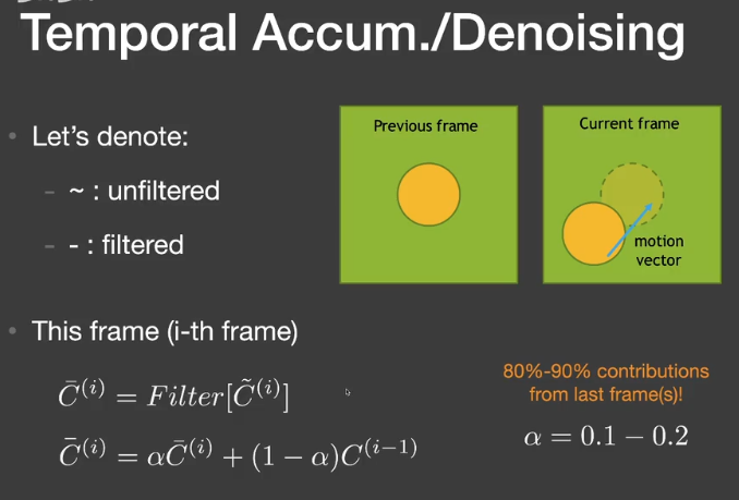
工业界的解决方案中最重要的是Temporal滤波
- 关键思路:
- 假设当前帧的前一阵是降噪的,因此可以复用。
- 使用motion vectors来找到前一帧的对应位置。
- 用上一帧的结果来计算当前帧结果。
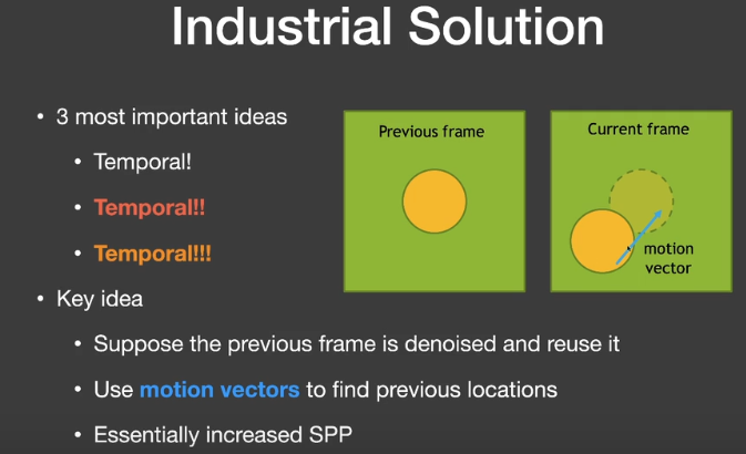
Motion Vector
G-Buffers(Geometry buffer)
在渲染过程中,可以获得一些额外的信息,如每像素的深度、法线、世界坐标等。生成G-buffer是比较容易的,只有屏幕空间信息。
Back Projection
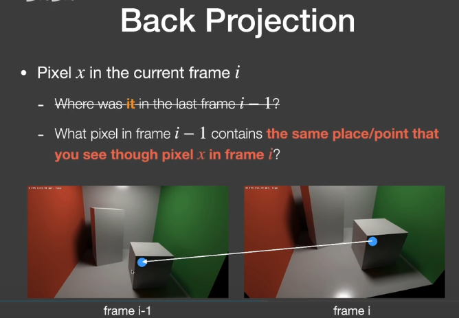
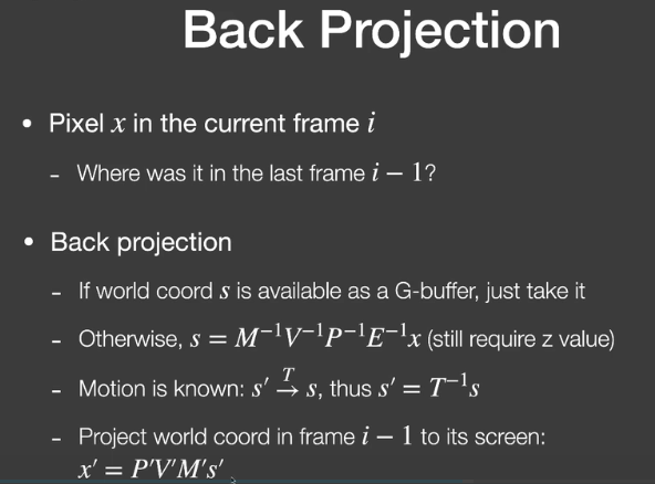
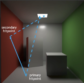
x’就是当前帧像素对应的世界坐标位置对应到上一帧该位置所在的像素。
Temporal accumulation/filtering
在这种1spp的结果下,回顾蒙特卡洛路径追踪,它的结果应该是无偏的,之所以看起来暗,是因为有很多的采样点原本的值是非常大的,但在显示器的clamp下,变成了1(255),因此看起来暗了。
Failure cases
Switching scenes(burn-in period)
切换场景、快速的镜头切换
Walking backwards in a hallway(screen space issue)
镜头中的信息是增加的
Suddenly appearing background(disocclusion)
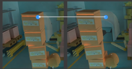
造成拖尾(Lagging)的结果
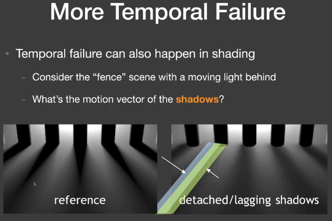
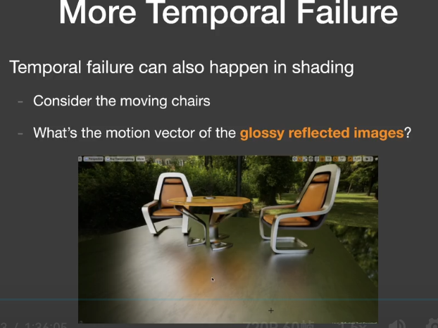
More Temporal Failure
Adjustments to Temp. Failure
2. Filtering techniques and implementation
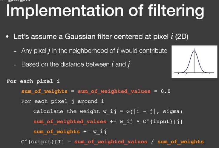
Implementation of filtering
- 图像低通滤波
- 消除了高频信号
- 只关注频域(Spatial domain)
- 图像+滤波器(filter kernel)->输出图像
- Gaussian filter
- 对于任何像素取周围范围的贡献,基于像素和周围的距离
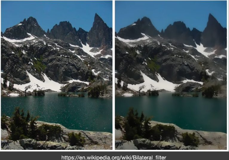
- Bilateral FIltering
- 背景
- Gaussian filtering 出现的问题是整体模糊,包括边缘
- 但是我们希望边界能够保持高频
- 边界<->理解为颜色剧烈变化的部分
- 思路
- 如何保留边界
- 如果像素j和i相差特别大,就让j对i的贡献减少
- 只需要控制kernel
- 背景
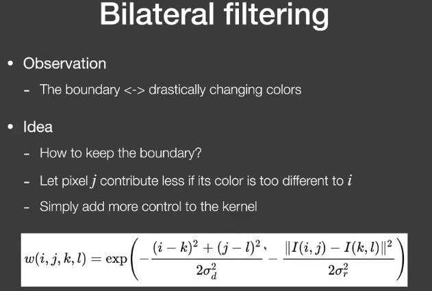
问题:如果噪声本来颜色差异就比较大,无法区分这部分噪声和边界。
Cross / Joint bilateral filtering
- Gaussian filtering以距离作为标准
- Bilateral filtering用位置距离、颜色距离作为标准
- 联合双边滤波采用更多的标准
- G-buffers
- Normal,depth,position,object ID,etc
- G-buffers是没有噪声的。
- G-buffers
- 特别适用于路径追踪的降噪
- Gaussian函数不是唯一的选择,任何随“距离”衰减的函数都可以,如Exponential(absolute),cosine(clamped)

Implementing Large filters
对于Kernel过大的情况
- Separate Passes
- 对于2D Gaussian filter
- 将它分成水平的pass和竖直的pass(N^2 ->N+N)
- 2D Gaussian filter kernel is separable
- $G_{2D}(x,y)=G_{1D}(x) \cdot G_{1D}(y)$
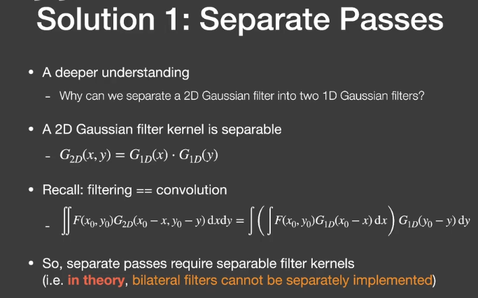
理论上双边滤波不能拆分实现。
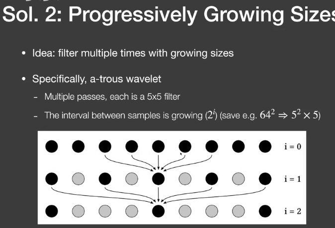
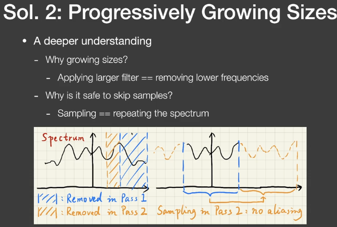
- Progressively Growing Size
- 用逐步增大filter进行多次滤波
- 为什么要用逐步增大的filter
- 去除更低的频率
- 为什么可以跳过一些samples
- Sampling= repeating the spectrum
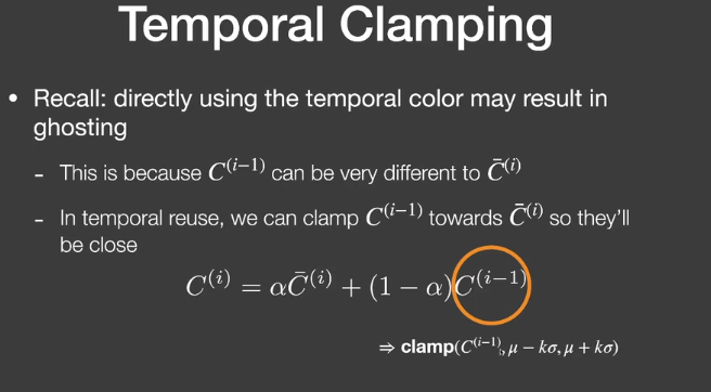
Outlier removal(and temporal clamping)
滤波后结果中还是会有一些特别亮的outlier(本来需要等更多的sample)
- 在滤波前去除outlier
- Outlier detection
- 计算像素neighbor的均值和方差
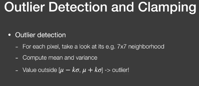
- Outlier removal
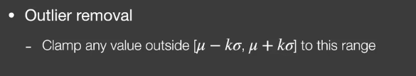
- Temporal Clamping
3. Specific filtering approaches for RTRT
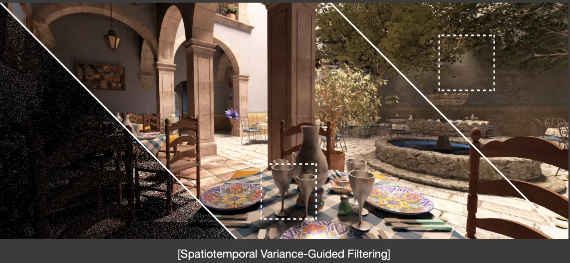
Spatiotemporal Variance-Guided Filtering(SVGF)
- similar to the basic spatio-temporal denoising scheme
- with some additional variance analysis and tricks
Joint Bilateral Filtering
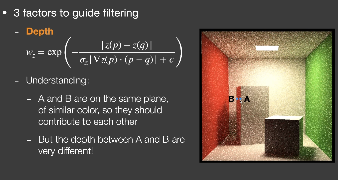
3 factors
Depth
- $w_z=\exp(-\frac{|z(p)-z(q)|}{\sigma_z|\nabla z(p)\cdot(p-q)|+\epsilon})$
Normal
- $$
w_n=\max(0,n(p)\cdot n(q))^{\sigma_n}
$$
- $$
Luminance(grayscale color value)
$$
w_l=\exp(-\frac{|l_i(p)-l_i(q)|}{\sigma_l\sqrt{g_{3\times3}(Var(l_i(p)))}+\epsilon})
$$Variance
- Calculate spatially in 7x7
- Also averaged over time using motion vectors
- Take another 3x3 spatial filter before use
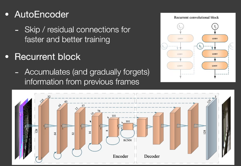
Recurrent AutoEncoder(RAE)
Interactive Reconstruction of Monte Carlo Image Sequences using a Recurrent denoising Auto Encoder
- A post-processing network that does denoising
- with the help of G-buffers
- The network automatically performs temporal accumulation
Key architecture design
Auto Encoder(or U-Net) structure
Recurrent convolutional block
【笔记】【GAMES202】Real-time Physically-Based Materials(Surface models)
Real-time Physically-Based Materials(Surface models)
PBR
PBR与PBR材质
PBR
- 一切基于物理,如材质、光照、相机、light transport等
- 不仅限于材质,但通常指材质
RTR中的PBR
- 实时渲染的材质种类、准确度等是不如离线的
- 实时渲染的PB通常并不真的physically based
RTR中的PBR材质
- Surface
- 大部分是微表面模型(使用错误,所以不太PBR)与Disney原则的BRDF(美术友好,但也不太PBR)
- Volumes
- 大部分关注性能和近似的single/multiple scattering(云、头发、皮肤等)
- 通常在使用上会使用很多hacks,并且非常关注性能
Microfacet BRDF微表面BRDF
在GAMES101中根据微表面模型提出了以下的BRDF模型吧
$$
f(i,o)=\frac{F(i,h)G(i,o,h)D(h)}{4(n,i)(n,o)}
$$
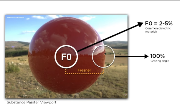
Fresnel
- 反射随着grazing angle(掠射角)增加会增多
在物理上需要考虑光线的极化-s极化与p极化
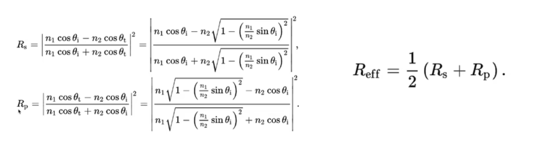
- 近似-Schlick’s approx
$$
R(\theta)=R_0+(1-R_0)(1-\cos\theta)^5
\R_0=(\frac{n_1-n_2}{n_1+n_2})^2
$$
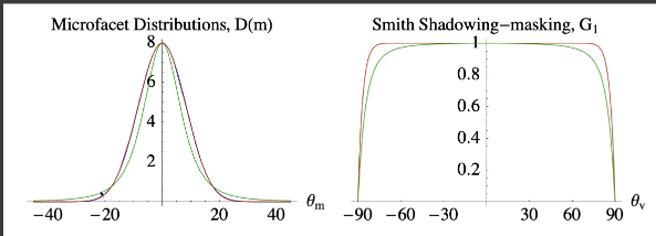
Normal Distribution Function
描述微表面的法线分布
法线集中
- Glossy-specular
法线分散
- Diffuse
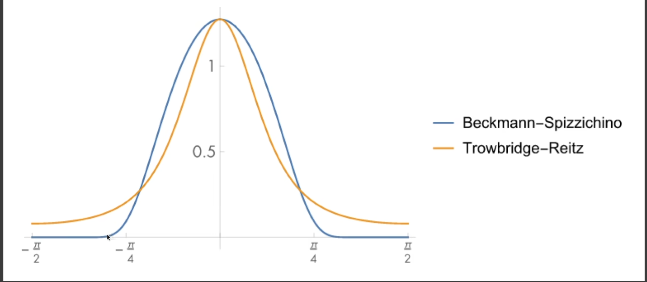
常用的法线分布函数模型
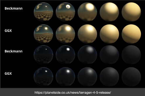
- Bechmann
- GGX
- 其他Detailed Model
Bechmann NDF
$$
D(h)=\frac{e^{-\frac{\tan^2\theta_h}{\alpha^2}}}{\pi\alpha^2\cos^4\theta_h}
$$
- $\alpha$: roughness
- $\theta_h$ : 半程向量h与法线夹角
- 近似于用高斯函数来建立模型,alpha描述了标准差,也即光滑程度
- 分母归一化保证了projected solid angle的积分域为1
- 定义在slope space(坡度空间)上
- 高斯函数的surpport(支撑集) 是无限大的,但可以映射到-90~90度的空间
- 描述的是各向同性的结果
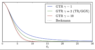
GGX(Trowbridge-Reitz)
- Long tail(拖尾表现更好)
- 过渡渐变看起来更自然
Extending GGX(GTR)
- GTR(Generalized Trowbridge-Reitz)
- 更长的拖尾
Shadowing-Masking Term
- Geometry term G(几何遮蔽项)
- 表示微表面自遮挡的数量,表现为入射光线被遮挡产生shadow,反射到眼睛的光线被遮挡为mask
- Shadowing-light
- Masking-eye
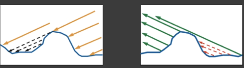
- 为什么需要几何遮蔽项
- 考虑如果没有G项,掠射角的入射和出射会发生什么?
- 根据Fresnel,在掠射部分的反射会变成1,
- BRDF分母接近0,最后的结果是在边缘部分接近白色,这是不合理的。
Smith Shadowing-masking term
假设法线为一种统计学分布模型,
- 将shadowing和masking的部分分开考虑
- 假设$G(i,o,m)\simeq G_1(i,m)G_1(o,m)$
问题
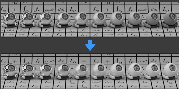
- 在Multiple Bounces(多次弹射)中产生的能量损失(在粗糙度高时更明显)
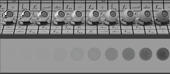
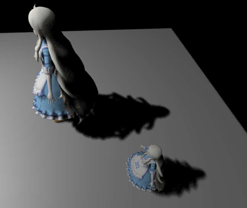
(如下图)在仅有的Uniform的全局光照下去照亮物体,对于specular的物体发生的正确反射,导致和背景融为一体。(白炉测试)
Roughness的部分会使反射光更容易被遮挡。因此在实际光线多次发生Bounce的过程中,只考虑一次Bounce,会导致能量损失

- Accurate methods[Heitz et al. 206]
- 在实时渲染中较慢
- Basic idea
- Being occluded = next bounce happening
- 被遮挡代表着下一次弹射发生
Kulla-county Approx
https://fpsunflower.github.io/ckulla/data/s2017_pbs_imageworks_slides_v2.pdf
依据经验来补全多次反射的能量
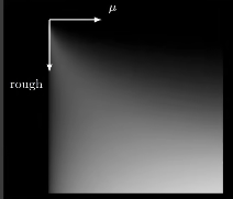
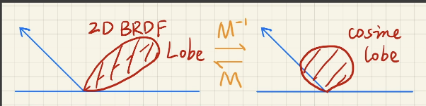
2D BRDF lobe中出射的总能量
$$
E(\mu_0)=\int^{2\pi}_0\int^1_0f(\mu_o,\mu_i,\phi)\mu_id\mu_id\phi
\\mu=\sin\theta
$$
在上式中注意$\mu d\mu d\phi$ 的部分,换成$\sin\theta$ ,即$\cos\theta\sin\theta d\theta d\phi$ ,也即球面参数化($\theta$, $\phi$)的表达。
- 丢失的能量
- 我们可以设计一个 additiional lobe,使得这部分积分为$1-E(\mu_o)$
- 出射的BRDF lobe和入射方向是不同的
- 考虑交换性,可以是如下形式$c(1-E(\mu_i))(1-E(\mu_o))$
$$
f_{ms}(\mu_o,\mu_i)=\frac{(1-E(\mu_i))(1-E(\mu_o))}{\pi(1-E_{avg})}
\E_{avg}=2\int_0^1E(\mu)\mu d\mu
$$
- $E_{avg}$ 的处理
- 对于复杂的积分,在split sum中,我们的处理方式是——precompute/tabulate预计算或制表
- $E_{avg}$ 的维度是多少 / $E_{avg}$ 有多少参数
- 只需考虑$\mu_0$ 和roughness
- 验证
$$
E_{ms}(\mu_o)=\int^{2\pi}0\int^1_0f{ms}(\mu_o,\mu_i,\phi)\mu_id\mu_id\phi
\=2\pi\int^1_0\frac{(1-E(\mu_i))(1-E(\mu_o))}{\pi(1-E_{avg})}\mu_id\mu_i
\=2\frac{1-E(\mu_o)}{1-E_{avg}}\int_0^1(1-E(\mu_i))\mu_id\mu_i
\=\frac{1-E(\mu_o)}{1-E_{avg}}(1-E_{avg})
\=1-E(\mu_o)
$$
- 以上的内容基于没有颜色(白色)的BRDF
- 但如果考虑其他颜色,也就代表着光线能量的吸收,也即能量的减少(损失)
- 因此我们只需要计算整体的能量损失
- 定义Average Fresnel平均菲涅尔
- 忽略入射角每次反射平均反射的能量
$$
F_{avg}=\frac{f_0^1F(\mu)\mu d\mu}{f_0^1\mu d\mu}=2\int_0^1F(\mu)\mu d\mu
$$
而$E_{avg}$ 代表我们能看到的能量(不参与多次bounce)
所以最后的能量可以分类为:
- 直接看到的能量$F_{avg}E_{avg}$
- 一次弹射后被看到的能量$F_{avg}(1-E_{avg})F_{avg}E_{avg}$
- ….
- k次弹射后被看到的能量$F_{avg}^k(1-E_{avg})^kF_{avg}E_{avg}$
相加起来的级数求和(这一部分直接和没有颜色的BRDF相乘)
$$
\frac{F_{avg}E_{avg}}{1-F_{avg}(1-E_{avg})}
$$
再来解释一遍带颜色的多次弹射的能量损失。
我们之间所做的计算都是基于没有颜色,也就是白色,也就是不吸收能量,所得到的结果。但是,如果物体存在颜色,也即会吸收能量,那么,在multi-bounces的过程中,每次弹射,都会吸收对应的能量,而我们用平均的菲涅尔来定义,这样就能忽略弹射的角度,而把所有的弹射加起来后,把这一部分由于颜色吸收能量带来的损失,和前面的乘起来,就是最后的结果。
Undesirable Hack
- 将Microfacet BRDF和一个diffuse lobe结合起来(在CV中的材质识别普遍使用)
- 这是不科学的(Cook-Torrance BRDF就是这么干的)
- 微表面已经将表面解释成表面的某种分布了,又怎么会加上一部分的理想漫反射呢
- 物理不正确,且能量不守恒
- (但也有加上diffuse后保证能量守恒的处理方式,这肯定也是存在的)
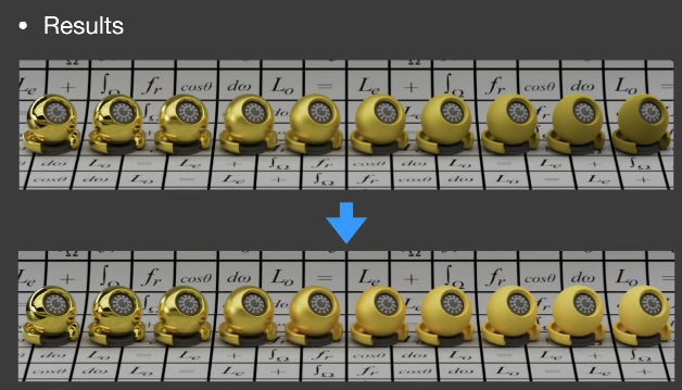
Linearly Transformed Cosines(LTC)
线性变换余弦方法——多边形光照下的微表面BRDF着色
解决microfacet model 的shading问题
主要基于GGX法线分布(其他模型也是可以的)
不考虑shadows
多边形光源
想法
- 任意2D的BRDF lobe可以被线性变换为余弦
- 光源的形状也可以被变换
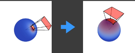
在cosine lobe上积分变换后的光源是有解析解的
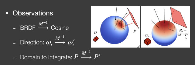
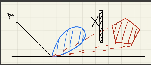
做法
认为多边形光源内部发出的光是uniform的,即Li是相同的,即从任意位置观察的多边形光源的Li是相同的
$$
\omega_i=\frac{M\omega_i’}{||M\omega_i’||}
\L(\omega_o)=L_i\cdot \int_PF(\omega_i)d\omega_i
\=L_i\cdot \int_P\cos(\omega_i’)d\frac{M\omega_i’}{||M\omega_i’||}
\=L_i\cdot \int_{P’}\cos(\omega_i’)Jd \omega_i’
$$
Disney Principled BRDF迪士尼原则的BRDF
- 微表面模型的缺陷
- 微表面模型不适合表现真实的物理材质
- 微表面模型缺少diffuse项
- 解释不了多层的材质
- 基于物理的参数艺术上不好用
- 反射率n-ik(复数)
- Disney Principled BRDF
- Art directable, 不要求物理上正确
- 实时渲染中认为是PBR的
- 需要使用更直接的参数,使用尽可能少的参数
- 参数最好是0-1的。如果有必要,也最好允许能够超出这个范围
- 所有有关联的参数应该鲁棒且合理
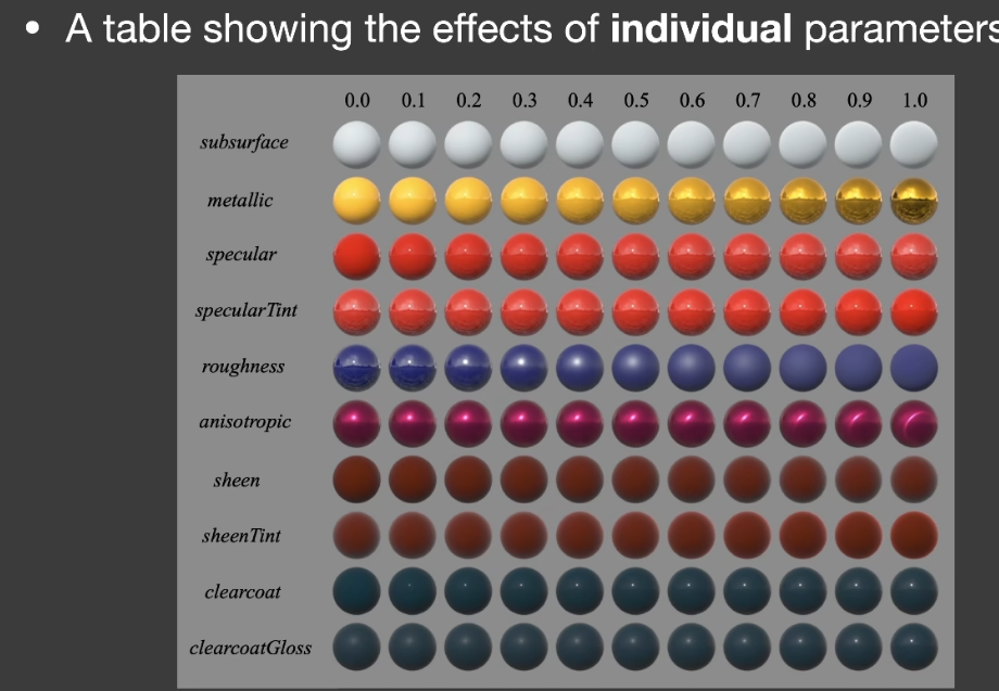
- sheen
- 类似天鹅绒的光泽效果
- clearcoat
- 清漆
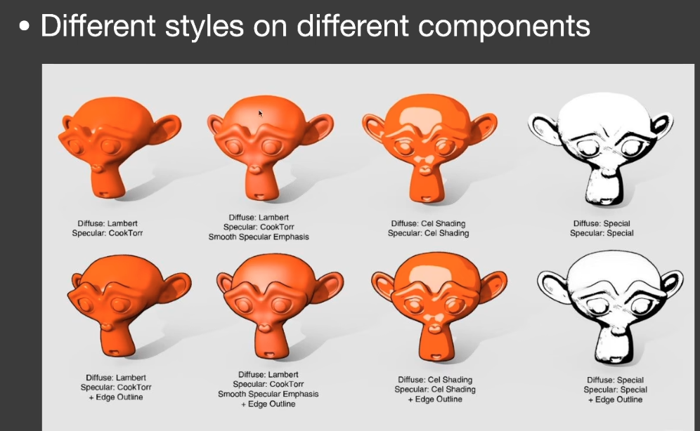
Non-Photorrealistic rendering(NPR)
NPR——stylization(fast and reliable)
- 来源于真实感渲染
- 利用抽象
- 强化重点
应用
- 艺术
- 可视化
- 指示说明
- 教育
- 娱乐
风格化
- 描边
- 阴影
- 色块
- 。。。
Outline Rendering
- 描边不只是轮廓
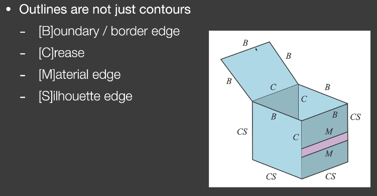
Boundary
Crease
- 折痕
Material edge
Silhouette
- 在物体外部轮廓上,要求有多个面共享的边界
shading方法
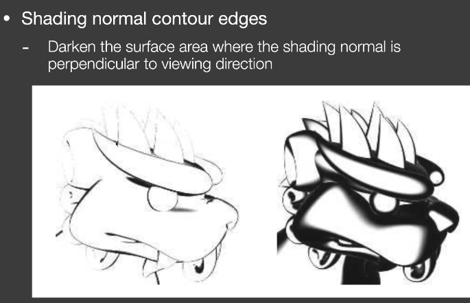
- 描边粗细不一致
Geometry方法
背面渲染成黑色沿顶点法线外扩
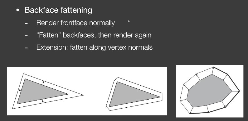
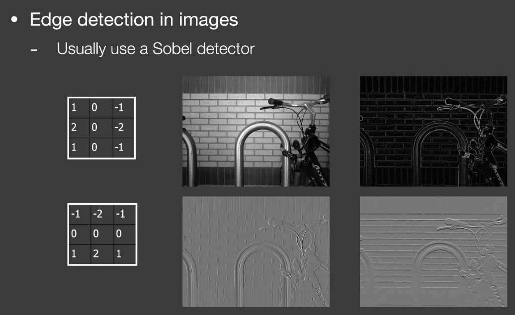
postprocess方法
图像边缘检测的方法
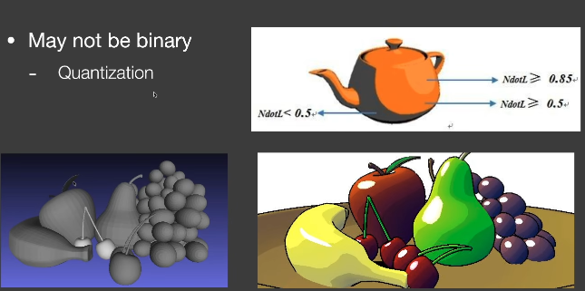
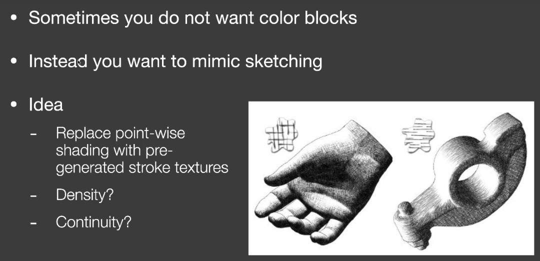
Color blocks色块
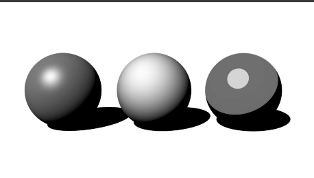
- Hard shading: thresholding on shading
- posterization: thresholding on final image
Strokes Surfaces Stylization
- sketch
【笔记】Cherno Opengl Tutorial note 04
24 Setting up a Test Framework
这次我们要对代码进行一些整理,为之后做好铺垫。
因为如果我们想让系统变得更复杂的话,像这样做是不行的。
首先清理下代码的结构
1 | int main(void) |
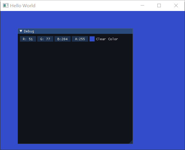
然后添加test
1 | test::TestClearColor test; |
就可以看到如下结果
test的部分结构如下
Test.h
作为Test的父类
1 |
|
1 | //TestClearColor.h |
这样就建立好了test的架构。
其实基于这个架构,我们可以做很多事了,例如在imgui上用菜单控制各种变量、贴图。。。
接下来我们要建立一个test的菜单,而不是直接打开test
25 Creating Tests
Test.h
1 |
|
Test.cpp
1 |
|
Application.cpp
1 | test::Test* currentTest = nullptr; |
我们运行后,啥都没有
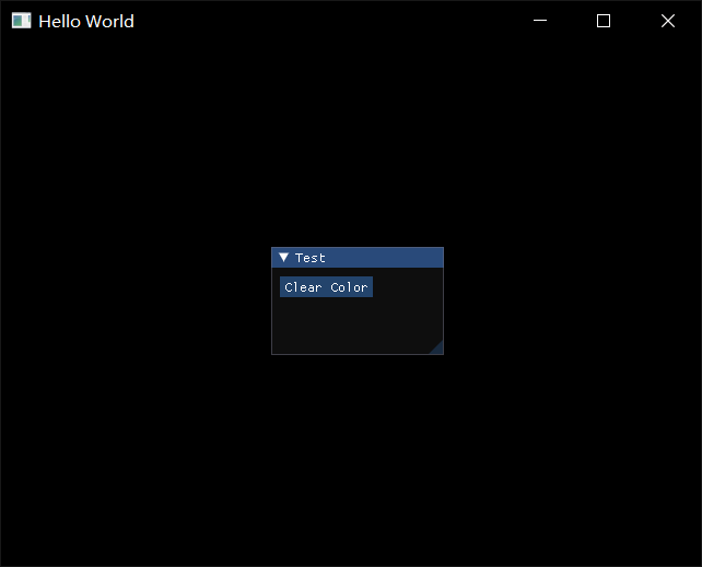
但是点击Clear Color的button以后,就获得了前面的Clear Color的功能,并且包含一个回退按钮,再点击这个回退按钮
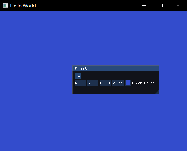
再点击这个回退按钮,这个Test实例就被注销了,并且UI也回到原来的界面,但由于Opengl是状态机修改,所以背景色的状态没有变回去
作者在循环开始时加上
1 | GLCall(glClearColor(0.0, 0.0f, 0.0f, 1.0f)); |
这样就能保证不存在TestClearColor实例时,有一个固定的背景色。(即注销实例后,背景色会清空)
为了防止内存溢出,在循环结束后,我们还要把new出来的test删掉
1 | delete currentTest; |
26 Creating a Texture Test
以上搭建的框架,其实就是建立了一个类似于沙盒,我们可以在里面设置各种测试Test
在之后的工作会进行Batch Rendering
1 |
|
TestTexture2D.cpp
1 | // |
在这里完成后,只需在main中注册。
Batch Rendering
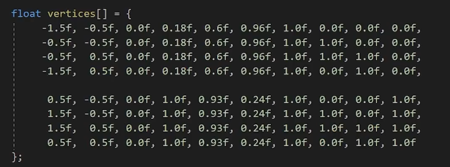
在处理Texture的时候要注意,由于最大的Texture slot数量的限制(比如上一章节讲texture里提过当前windows最大的数量32),同一个batch往往不能容纳足够的Texture,那么只能把多余的texture对应的网格渲染放到下一个batch,以此类推。
假如100个submesh,对应100个texture,每32个texture对应的mesh合批,这样也只需要4个drawcall
静态合批大抵就是如此(把不同mesh的vertex组合起来)
Dynamic Geometry
这一段就是讲动态合批。
静态合批是我们一开始就设定好了合批的数据,每一帧只需要渲染这些已经传递到GPU的数据。
而我们希望对于动态的物体也能进行合批。
重要的依然是这两部分:vertex buffer和index buffer
除了提前准备了这一部分数据,我们还使用
1 | glBufferData(GL_ARRAY_BUFER,sizeof(vertices),vertices,GL_STATIC_DRAW) |
在update前将数据储存到GPU。
而为了动态改变数据,我们可以只创建buffer,但是先不传递数据,即传递一个空指针。
我们也可以根据我们的顶点结构和需要的顶点数量来决定buffer的大小。
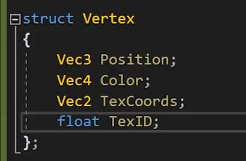
1 | struct Vertex{ |
最后就是绘制方式,不再是Static,我们要换成dynamic
1 | glBufferData(GL_ARRAY_BUFER,1000*sizeof(Vertex),nullptr,GL_DYNAMIC_DRAW) |
其他关于顶点属性绑定之类都是一样的,只不过可以利用Vertex的结构来让它变得更通用
1 | glEnableVertexArrayAttrib(m_QuadVB,0); |
IB在合批中也不应该被改变。虽然我们动态地改变了顶点的属性,但是这些跟IB有什么关系。
在数量庞大的vertices当中,往往也需要用for loop来构建indices。(去年可视化的性能优化工作就是手动做了静态合批这件事……虽然当时并不知道合批这个概念)
Update
1 | //Set dynamic buffer |
然后我们就可以通过各种方式来改变绘制的顶点数据
比如通过gui来控制
1 | //OnImGuiRender |
这样就完成了动态的vertex buffer绘制,以及动态合批,我们只创建了一个vertex buffer,调用了一次drawcall。
Indices
对于两个quad,我们很简单地就可以直接写出合批的indices
1 | uint32_t indices[] = { |
但是对于数量更多的mesh,我们也可以有一定的规律来写出。
首先依然要决定我们要绘制多少个四边形,以1000个为例
1 | const size_t MaxQuadCount = 1000; |
【笔记】Cherno Opengl Tutorial note 03
16 Writing a Basic Renderer
目前为止,如果我们每次想要绘制东西,都需要完成所有步骤-绑定-drawcall
希望能够提供
Renderer
unbind不是绝对的,但在debug中很有用,也许也能减少一些错误。但是实际上没有必要要,因为绑定下一个对象,就等于解绑了。
Renderer
要注意Renderer.h这里有一些小坑,就是作者include了VertexArray.h,其中又include了VertexBufferLayout。但是之前为了方便把debug的函数写在了Renderer当中,导致这里出现了相互include。解决方法就是把VertexArray.h中对VertexBufferLayout的include去掉,改成对这个class的声明,然后因为VertexArray.h还是需要使用其内部方法,在VertexArray.cpp 中再include VertexBufferLayout。
1 | //Renderer.h |
drawcall
1 | while (!glfwWindowShouldClose(window)) |
这样我们在renderer当中有顶点数组和索引缓冲区以及一个shader。
但是相比于shader,在传统的渲染器中采用的是材质material。材质就是shader加上一组数据(uniforms)。
这样将material传递给renderer,它将直接把shader和uniform绑定,然后再进行drawcall。。。
在本教程中也许不会涉及,但是在Game Engine中一定需要做。
17 Textures
我们会忽略游戏中使用的纹理格式,但反正肯定不是png
- 将图片加载到cpu memory
- 将pixel array 传递到GPU
- 使用shader读取到texture
我们这里将会使用#include <stb_image.h>来处理png图片
stb/stb_image.h at master · nothings/stb (github.com)
(直接拿图形学课的框架里的用了),我们实际上只需要使用stb_image.h
在项目中新建stb_image.h和stb_image.cpp文件,把头文件直接复制进去,并且根据注释说明,在cpp文件中添加
1 |
这样就可以使用了。
然后我们要添加texture类
1 | //Texture.h |
Texture.cpp
1 | //Texture.cpp |
这中间还有一些需要修改的,比如uniform、shader中的varying变量(in、out)
1 | void Shader::SetUniform1i(const std::string& name, int value) |
当画出来的屏幕是黑的时候,加上GLCall()来debug就显得非常好用了
直接提示到我们
是这句发生了错误
1 | glTexImage2D(GL_TEXTURE_2D, 0, GL_RGBA8, m_Width, m_Height, 0, GL_RGBA8, GL_UNSIGNED_BYTE, m_LocalBuffer); |
根据文档,这里两个format分别是internal format和format。internal format是opengl储存纹理的方法。format是提供的纹理的格式。所以我们提供GL_RGBA8告诉opengl储存单通道8位。而我们提供的纹理则是GL_RGBA格式的。
这样就非常完美地画出了薰。
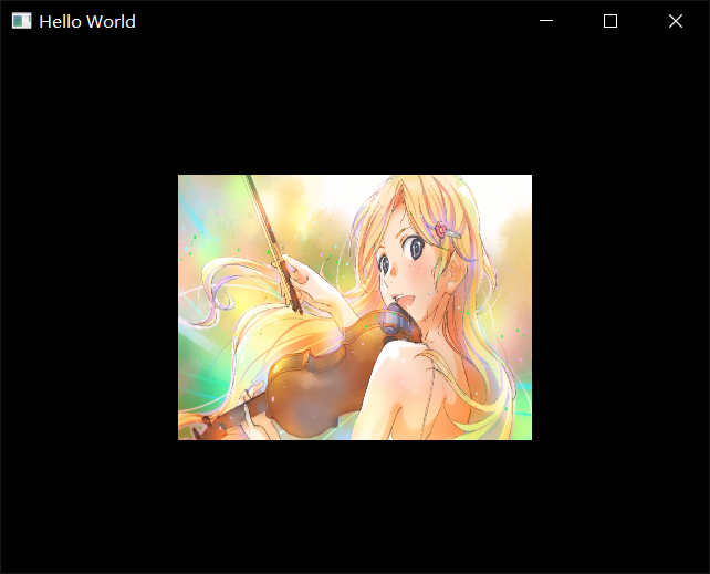
(作者由于透明度混合设置的问题,图片出现了失真。)
1 | glBlendFunc(GL_SRC_ALPHA, GL_ONE_MINUS_SRC_ALPHA); |
18 Blending
Blending determines how we combine our output color with what is already in our target buffer.
- output
- the color we output from our fragment shader
- Target buffer
- the buffer our fs is drawing to (destination)
如何控制Blending
- glEnable(GL_BLEND)-glDisable(GL_BLEND)
- glBlendFunc(src, dest)
- src = how the src RGBA factor is computed(default is GL_ONE)
- dest = how the dest RGBA factor is computed(default is GL_ZERO)
- glBlendEquation(mode)(BlendOp)
- mode = how we combine the src and dest colors
- Defualt value is GL_FUNC_ADD
19 Maths
ignored
在该教程中会使用glm(适用于opengl的数学库)。并且适配与opengl列主序的矩阵。
通常在我们自己写跨平台的引擎时,也会自己写数学库。可以是行主序的。
Releases · g-truc/glm (github.com)
我们可以在glm的git上下到release版,这里还是就直接把之前的复制到Dependencies里了。
实际上我们只需要glm文件夹里的东西。
作者把它也放进了vendor文件夹里。
(其实我也更倾向放到Dependencie里作为附加包含目录)
GLM也是一个只包含头文件的库,没有cpp文件,不需要编译
事实上,作者随后就把vendor文件夹放到了附加包含目录里。。。
20 Projection Matrices
在projection中我们完成了归一化齐次坐标[-1,1]^3
略了
21 Model View Projection Matrices
1 | glm::mat4 proj = glm::ortho(-2.0f, 2.0f, -1.5f, 1.5f, -1.0f, 1.0f); |
在这里对view的处理很简单,就是我们向右移动相机,等同于向左移动物体。
22 ImGui
环境配置
这里只是简单地将imgui移植到我们的opengl中,
下载到release的source code
它提供了我们一个vs工程文件和一大堆各种平台的项目,我们也可以在这里面找到关于glfw_opengl3的example
而我们实际需要的是根目录下的那些头文件和cpp文件。总之我们把他们复制到vendor中的imgui文件夹,就可以用了。
我对比了一下这里的以及图形学课用的框架里的,多了这四个文件
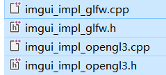
可以看到这是imgui对glfw和opengl的实现(implementation)。在作者下载的imgui版本中,它们存在于examples当中(opengl3_example),但是我这里下载的版本已经更新了。
找了一下,它们已经更换了目录结构,现在这些impl文件都在backends文件夹中
所以我们还是得把这四个文件复制过去。
作者的版本当中的imgl_glfw使用了gl3w,有提示需要改成glew,但在我们这里没有这个问题。
但我们编译时会发现它新增了一个
1 | // Modern desktop OpenGL doesn't have a standard portable header file to load OpenGL function pointers. |
意思就是。。。他们还是自己搞了一个gl3w,并且封装在这个loader头文件中了。。。我们直接删掉这是两行换成glew,看看理解对不对
1 |
如下
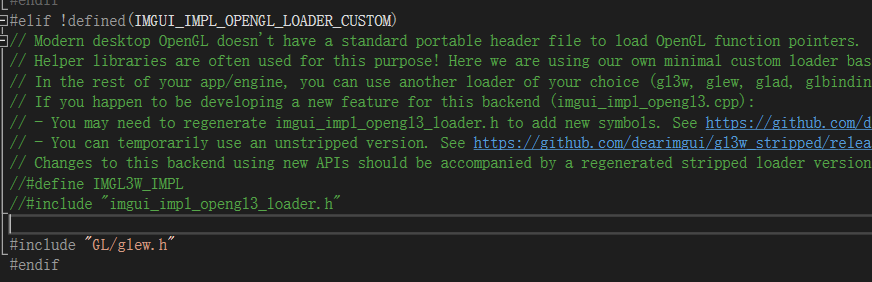
然而不对,这里后面会用到gl3w的api
OpenGL 后端现在嵌入了自己的 GL 加载程序 (imgui_impl_opengl3_loader.h) ·问题 #4445 ·ocornut/imgui (github.com)
后来感觉这样还是不行,loader里面就是对gl3w的实现了,我们应该直接换glew。因此注释掉上面两行以后,定位到接下来的问题
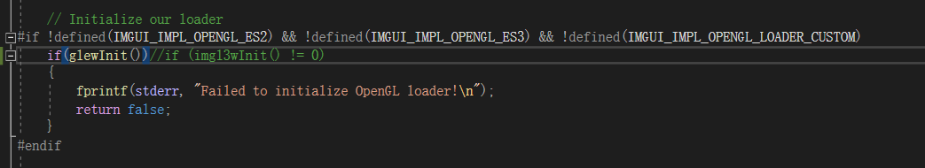
对于这里的初始化,我们直接给换成glewInit。这样就顺利运行了。
还是踩了些小坑,麻烦的话就直接跟着教程版本一致就好了。
使用imgui
我们还是可以参考example中main里面的实现。
1 | // Setup Dear ImGui context |
和教程里面稍有变化(瑟瑟发抖,感觉坑会越来越多了,有点后悔),幸好和图形学课里的框架还是比较接近的,还算能参考一下。
助教的框架向上再封装了一层。这个教程这里大概是为了简单,直接写在了main函数里。
直接把上面的初始化复制上去,然后回头添加头文件
1 |
还有个glsl_version变量,在example里面是定义的。但是我们去这个函数里看一看,其实如果直接给NULL的话,是有默认值的。
1 | // Store GLSL version string so we can refer to it later in case we recreate shaders. |
并且注释很贴心地告诉我们,如果不确定glsl的版本,就直接留空
所以这个glsl_version变量我们直接删掉。
虽然和教程里面不一样,会多一些步骤,但像这样自己解决掉问题还是会很有成就感的吧,其实也不难对吧。
(实际上作者也跳过了里面io的初始化,这个我们也可以删掉)
然后是循环中的newframe步骤(作者仅需一行,我们这里变成了三行)
1 | // Start the Dear ImGui frame |
关于位置,助教框架的做法是——先渲染画面,再渲染gui。这一部分放在一个renderframe函数中,向上封装的流程是——输入输出处理-renderframe-swapbuffer-pollEvent
这也很符合逻辑,我们就也把这部分放在交换缓冲之前好了。(其实作者提出放哪里都行,只要Imgui的代码是放在这里面end之前就好了)
然后我们添加render命令
1 | ImGui::Render(); |
在循环结束后,我们还要shutdown
1 | ImGui_ImplOpenGL3_Shutdown(); |
然后关于gui里的具体内容我们就复制一下example的就好了
1 | { |
(还有三个小变量,直接复制一下就好了)
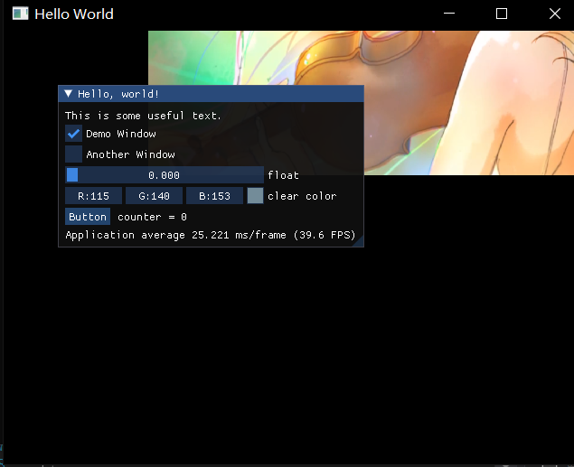
非常好用。
然后我们要开始改造自己需要的gui了。
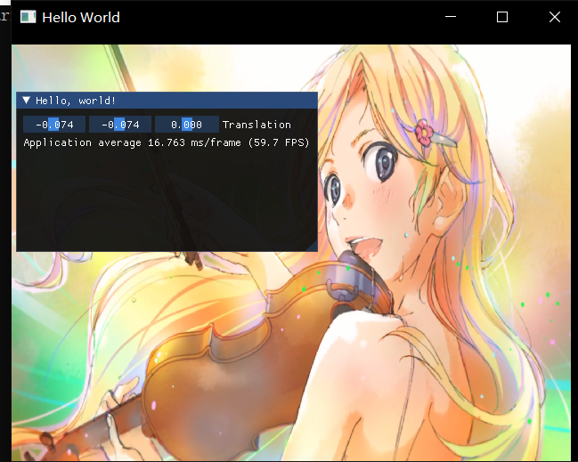
1 | glm::mat4 model = glm::translate(glm::mat4(1.0f), translation); |
我们把model的修改移动到主循环当中,也非常好用。
这里我们使用的Float3,只提供了第一个translation.x 的指针。在使用的时候我们也要注意,glm::vec3这种结构储存的数据在内存上是不是连续的。
23 Rendering Multiple Objects
回顾我们之前的drawcall的部分,主要是这几个步骤
1 | shader.Bind(); |
分析shader当中,我们想要画出另一个位置的物体,我们可以提供一个不同的vertex buffer
那么当然也可以使用另一个mvp(这当然也更快)。
当我们要绘制同一个物体很多次时(如tile类型的这种东西)我们没有必要用for loop像这样去绘制很多次,而是可以用==batching== 合批的方法,只调用一次drawcall,把所有的东西放到一个vertex buffer里。